Home /
Expert Answers /
Electrical Engineering /
i-implemented-a-4-bit-shift-register-using-d-flip-flop-on-the-breadboard-but-how-do-you-implement-t-pa961
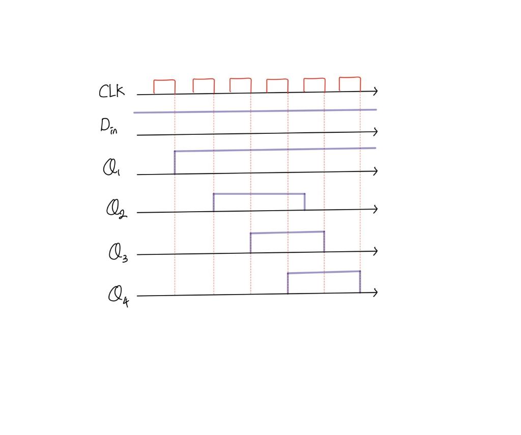
(Solved): I implemented a 4-bit shift register using D flip-flop on the breadboard. but How do you implement t ...
Expert Answer
To generate the timing diagram for a 4-bit shift register implemented using D flip-flops, you need to understand the behavior of the circuit and the input waveform. The D flip-flop c...