Home /
Expert Answers /
Electrical Engineering /
4-consider-the-block-diagram-of-a-robot-arm-control-system-shown-in-fig-p8-6-4-below-the-input-pa621
(Solved): 4. Consider the block diagram of a robot-arm control system shown in Fig. P8.6-4 below. The input ...
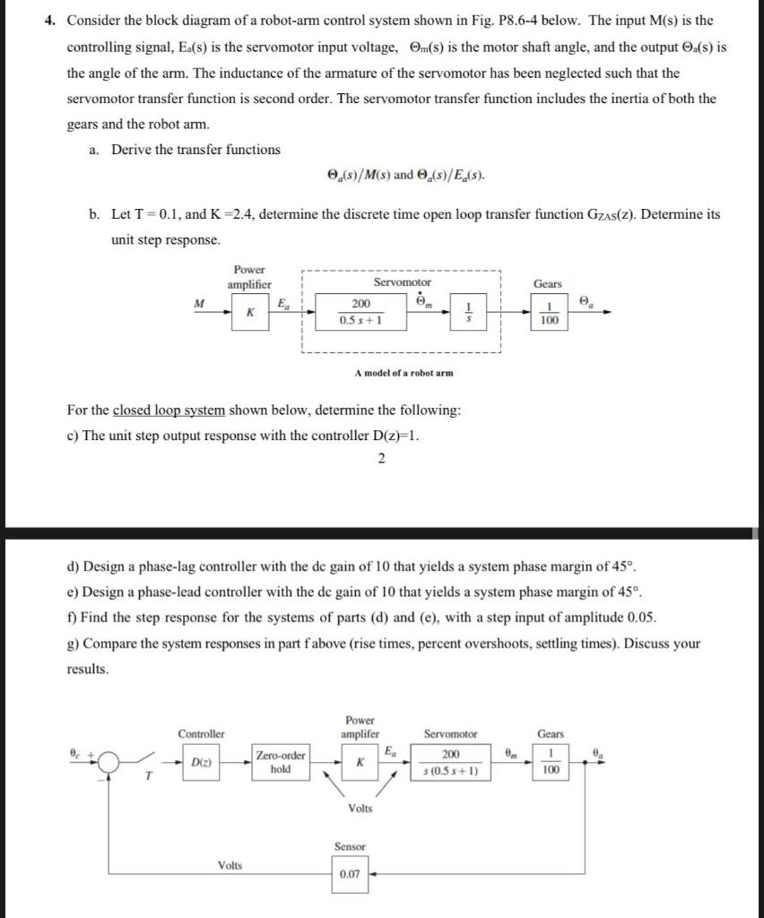
4. Consider the block diagram of a robot-arm control system shown in Fig. P8.6-4 below. The input M(s) is the controlling signal, is the servomotor input voltage, is the motor shaft angle, and the output is the angle of the arm. The inductance of the armature of the servomotor has been neglected such that the servomotor transfer function is second order. The servomotor transfer function includes the inertia of both the gears and the robot arm. a. Derive the transfer functions b. Let , and , determine the discrete time open loop transfer function . Determine its unit step response. For the closed loop system shown below, determine the following: c) The unit step output response with the controller . 2 d) Design a phase-lag controller with the dc gain of 10 that yields a system phase margin of . e) Design a phase-lead controller with the dc gain of 10 that yields a system phase margin of . f) Find the step response for the systems of parts (d) and (e), with a step input of amplitude 0.05 . g) Compare the system responses in part f above (rise times, percent overshoots, settling times). Discuss your results.
Expert Answer
To derive the transfer functions, we'll first identify the individual components in the block diagram and then apply block diagram reduction techniques.
